Jump to content
  • Sign Up

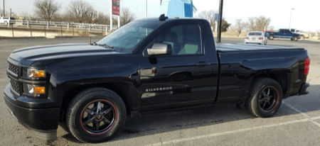
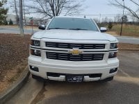
WT trim with Color DIC, Steering Wheel Controls, IO5 Stereo retrofit.


Recommended Posts


IPC only and you'd be supplying a new IPC anyhow so shipping yours isn't an issue, there is no downtime etc.

Thanks! Is this the same for BCMs as well?


Sent from my iPhone using Tapatalk

Link to comment
Share on other sites

  • 2 weeks later...

Hey man hope you can help me with a problem I'm facing, I added a steering wheel with controls and intended to connect the controls to my aftermarket stereo but I don't have the right harness do you know the part number? It would help me a lot , thanks.

Edited by KWT-GM
Link to comment
Share on other sites

  • 2 months later...

Guys not to beat a dead horse but please contact us to check fitment BEFORE purchasing a cluster for this retrofit. They ARE model year specific even though they look the same on the outside; we want to make sure you get the right parts for your conversion :)

  • Like 2
Link to comment
Share on other sites

GTPprix, can you program window up/down with the key fob for a '14 LT? I've emailed multiple times on the weekend with no response and I can't PM you on here.


Matt,


Unless someone else has a similar build and last name you replied to our request for more information regarding the vehicle build (express on the passenger side) and didnt reply after pricing was sent. Not sure how thats no response? Contact us this weekend and we'll go over it all again if you'd like.

Edited by GTPprix
Link to comment
Share on other sites

So you're not Matt B**** with a CBR related email address at yahoo? ;) Because if not you have an electronic doppelgänger asking for the exact same thing on a 2014 that replied to our reply LOL


Drop us a line either way :)

Edited by GTPprix
Link to comment
Share on other sites

Now that this post has aged a little feel free to contact me directly (IM on here) if you have additional questions on wiring this in as I won't be following the thread as closely. Compatibility is Chris's (GTPrix) domain as I don't even understand what's going on with all the different gauge cluster part numbers!

Edited by Darth_Vader
Link to comment
Share on other sites

I'm going to give this a shot in the near future, I already went from I04 to I06 and successfully retrofitted powerfolding mirrors on a base WT. So wiring isn't to scary, I hope you will still be around to reply when I actually do it, but as long is this post stays, I'll probably figure it out.


Thanks!!

Link to comment
Share on other sites

  • 2 months later...

Well after some work and some digging and some wiring I have finally completed the retrofit of my RCSB Blackout (Which was the WT trim with the small radio) to have the IO5 stereo, Color DIC Gauge Cluster and Heated Steering wheel with all the controls working, both the DIC and the stereo controls work. I would guess that total I have about $2000 tied up in all of this so it can get costly and it isn't for the feint of heart, you will be cutting into factory wires. This will only work if you have the IO4 option code, if you have the IO3 stereo you are probably out of luck.


Gauge cluster programming was provided by Chris over at WAMS, I highly suggest going to Chris for all your custom module programming needs. He is a busy guy so if you have questions on this swap you will want to post them here as Chris won't be able to help you out with anything other than providing the custom programming for the cluster. You can request prices from his site at: http://www.whiteautoandmedia.com/


All of the information needed to do this retrofit can been dug up from the upfitters electrical manual available at: https://www.gmupfitter.com/pages/body-builder-manuals

If you plan on attempting this familiarize yourself with the information I post and this manual, it will save you some head aches.


Basically all you are doing is tying back the steering wheel controls to the gauge cluster on the LIN Bus (one wire, that doesn't exist if you don't have controls) and then adding the gauge cluster to the MOST bus via the stereo. This is easily done at the radio module behind the HMI (The top box, but you know this if you have upgraded to IO5 or IO6) just with the grey 8 pin connector which actually is where it shows the gauge cluster being in relation between the amplifier and the radio. You will want to put the gauge cluster in series on the most bus on wires 3 and 4 from the far right connector on the radio module. So basically you will cut these wires and where they were going in to the radio now they will go into the gauge cluster on pins 1 and 2 and the return to the radio from pins 17 and 18 on the gauge cluster, all this can be found in the upfitter manaul. Then you will want to grab the MOST enable signal from wire 7 on the connector and bring it back to the gauge cluster also, you can tap off of it.


If you have any questions feel free to post them here and I will try to stop in every so often and answer. PM's will go unanswered as I don't want to type the same info out 20 times so just post it here so we can have one post covering this. I will also try and post some diagrams and more pictures next week along with a link to the pins that plug in to the blank spots on the connector of the gauge cluster to add the above circuits.


But yes, this can be done.


Thanks,

Kyle


Gosh!

I'm terrible at reading circuit flow charts.

I want to clarify 1 thing. When I cut the cables from the radio connector. (I'm attempting to post a pic of the radio connector, i hope it shows.)

well here's the link for the pic

These 2 cables will now go into the gauge cluster.

  • Aren't pins 1 and 2 occupied on the gauge cluster?
  • If so, do I solder or tap them in?

If they aren't occupied I will just take the terminal and crimp it to the wire and insert it to the gauge connector.

Then these 2 wires will return back to the radio connector pins 3&4 via gauge connector pins 17&18. Correct?

Link to comment
Share on other sites


Gosh!

I'm terrible at reading circuit flow charts.

I want to clarify 1 thing. When I cut the cables from the radio connector. (I'm attempting to post a pic of the radio connector, i hope it shows.)

well here's the link for the pic

These 2 cables will now go into the gauge cluster.

  • Aren't pins 1 and 2 occupied on the gauge cluster?
  • If so, do I solder or tap them in?

If they aren't occupied I will just take the terminal and crimp it to the wire and insert it to the gauge connector.

Then these 2 wires will return back to the radio connector pins 3&4 via gauge connector pins 17&18. Correct?


Shouldn't be anything on pins 1 and 2 if you had the monochrome cluster before hand. But you are right on the rest. Basically the wires on the connector in your picture as listed on my original post are split with the harness side going to pins 1 and 2 on the cluster instead of the radio and then the return from the cluster will go directly into the radio where the wires were going. You are just paralleling the cluster with the radio on the MOST bus.


Good luck!

Link to comment
Share on other sites


Shouldn't be anything on pins 1 and 2 if you had the monochrome cluster before hand. But you are right on the rest. Basically the wires on the connector in your picture as listed on my original post are split with the harness side going to pins 1 and 2 on the cluster instead of the radio and then the return from the cluster will go directly into the radio where the wires were going. You are just paralleling the cluster with the radio on the MOST bus.


Good luck!

Sounds easy enough, thanks for being prompt and very helpful. I might have more questions later. You're the man!

Link to comment
Share on other sites

Join the conversation

You can post now and register later. If you have an account, sign in now to post with your account.

Guest
Reply to this topic...

×   Pasted as rich text.   Paste as plain text instead

  Only 75 emoji are allowed.

×   Your link has been automatically embedded.   Display as a link instead

×   Your previous content has been restored.   Clear editor

×   You cannot paste images directly. Upload or insert images from URL.


×
×
  • Create New...

Important Information

By using this site, you agree to our Terms of Use.