Search the Community
Showing results for tags 'upfitter switch'.
-
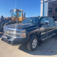
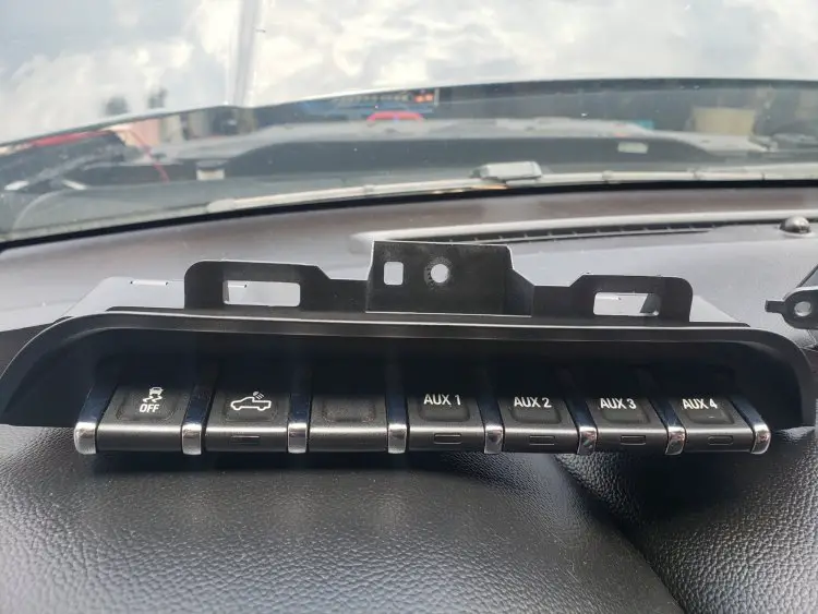
Hey all, Hoping to upgrade my switch - From just 'Traction Control' and 'Cargo Lights' to the upfitter switch 84347196 that has those two switches plus 4 aux switches (pic 1). There is a pretty extensive thread on this already but it is long and jumbled with no clear summary, I am also no expert on any of this so hard to understand half of it! So hoping to run my plan by y'all and see if you think this will work. 2018 Silverado 2500HD 6.0L Parts: Aux Switch Part #84347196 (4) Pre-Terminated Leads - Available from HarnessDr (pic 2) 4 Relay Panel with Flyback Diodes (mgispeedware.com/product/automotive-relay-panel-spst-on-sale/) (pic 3) Plan: 1. Remove existing "Traction Control" and "Cargo Lights" switch. Remove two harnesses from back of the old switch. 2. Take the four pre-terminated leads and insert into the larger harness, spots 10, 11, 12, 13 (currently empty because truck did not come with upfitter switch). You will have to pop the harness latch off to do this (pic 5). 3. Extend off the 4 leads I just installed and run them all the way up to relay location. 4. Install relay bank including mounting and running power and ground wires for the relay bank. 5. Connect the signal leads from the aux switch to each individual relay. Key is to make sure setup as a "ground trigger" on the relay as these switch wires do not have positive voltage (pic 4). Setup like load 1 and 2 in pic 4.. 6. Run power to the intended accessories from the relay, good to go! Couple of questions. Is this the right relay setup for ground switching? Will these wires work as ground switches? Also, in the big thread on this there was mention of using diodes to prevent damage to the aux switch. I've never wired a diode into automotive wiring but if that works please let me know a good part #. I'm also not sure what direction the diode would need to point as it is a ground trigger. I ordered the relay panel with "flyback diodes" thinking it will accomplish protecting the switch, but not 100% sure that is the right setup to protect a ground trigger... Thank you to anyone who read this whole thing and thanks in advance for any input!
-
here are some picture and videos of how i installed my upfitter aux switches to my 2017 silverado Texas edition truck which DID NOT com with them nor does it have the relays fuses or switch wires in the harness. keep in mind the switches are GROUND or NEGATIVE switching. which means they DO NOT HAVE 12v ON THEM. DO NOT PUT 12V ON THE WIRES YOUR ABOUT TO INSTALL. i had to get a new connector from a crashed truck in a junk yard which i then pulled 4 of the pins and wires out of to install into my trucks harness plug for the upfitter switch. once i did that it was just a simple act of making a short extension wire from those 4 wires coming from the harness plug to go to the driver kick panel where im going to locate the relays for the devises i want to control. you will see the harness plug and wires where i put them. and you will see the JST plug i used to connect the 4 wires to the extension wire to run to my relays. will also upload videos soon.
-
Morning, It was suggested that I place the write up on the custom gauge installation in this section so I will do just that. A bit of background: this truck is brand new with just under 8000 km on the clock. It has already seen -45C and some off road conditions. I am a business owner (Arrowsmith Project Management Limited) and this is one of my trucks. First: a special thanks to everyone who has discussed the upfitter switches using the GM parts. I was very excited about that and was going to go that way but with discussions at the local parts counter about being my responsibility and that it would void the warranty and such I decided to do my own thing as all of this 12V stuff just needs a source and a ground. No ECM or other modules to plug into etc. Second, because I bounce down roads everything has to be solid, secure and of industrial grade to not fall apart in the middle of nowhere. Here is the installation process. FYI get the right tools - in this case the trim removal tools or you could end up with scratches and nicks like this. (PIC 1) PIC 2 and 3 - OEM trim of the AT4 before PIC 4 and 5 - Pay close attention to how things come apart - watch all the videos and read all the existing write ups on removal of panels. This TAKES TIME. Go slow and be patient. There are 2 clips that will break if your removal of the console lower trim piece on either side is removed in haste. PIC 6, 7 and 8 - The removal process. PIC 9, 10, 11 and 12 - Switch locations and layout - plan this out carefully. measure as many times as you need to. Take lots of pictures. I opted to use the OEM location as best I could for 2 switches. These ones control my front light bar from Bright Source and Strands. It has a main ON/OFF and a secondary driving light in both amber and white. This resulted in first installing a SPST rocker and a SPST moment switch. The moment was later swapped out for a SPDT rocker. I had a little trimming to do under the knee bolster panel. PIC 13, 14 and 15 - Trimming the drivers side lower console panel - this was done to house the cluster of switches for all the other goodies I need. (Reverse Alarm (1), Buggy Whip (1), Overhead Rotating Beacon (2), winch (1) and rear facing service lights (1))


.thumb.jpg.1af0fedf68068d41639e1cf539e8df4d.jpg)


